I. Heat exchanger classification:
Shell and tube heat exchanger can be divided into the following two categories according to the structural characteristics.
1. Rigid structure of the shell and tube heat exchanger: this heat exchanger has become a fixed tube and plate type, usually can be divided into single-tube range and multi-tube range of two kinds. Its advantages are simple and compact structure, cheap and widely used; disadvantage is that the tube can not be mechanically cleaned.
2. Shell and tube heat exchanger with temperature compensation device: it can make the heated part of the free expansion. The structure of the form can be divided into:
① floating head type heat exchanger: this heat exchanger can be freely expanded at one end of the tube plate, the so-called "floating head". He applies to the tube wall and shell wall temperature difference is large, the tube bundle space is often cleaned. However, its structure is more complex, processing and manufacturing costs are higher.
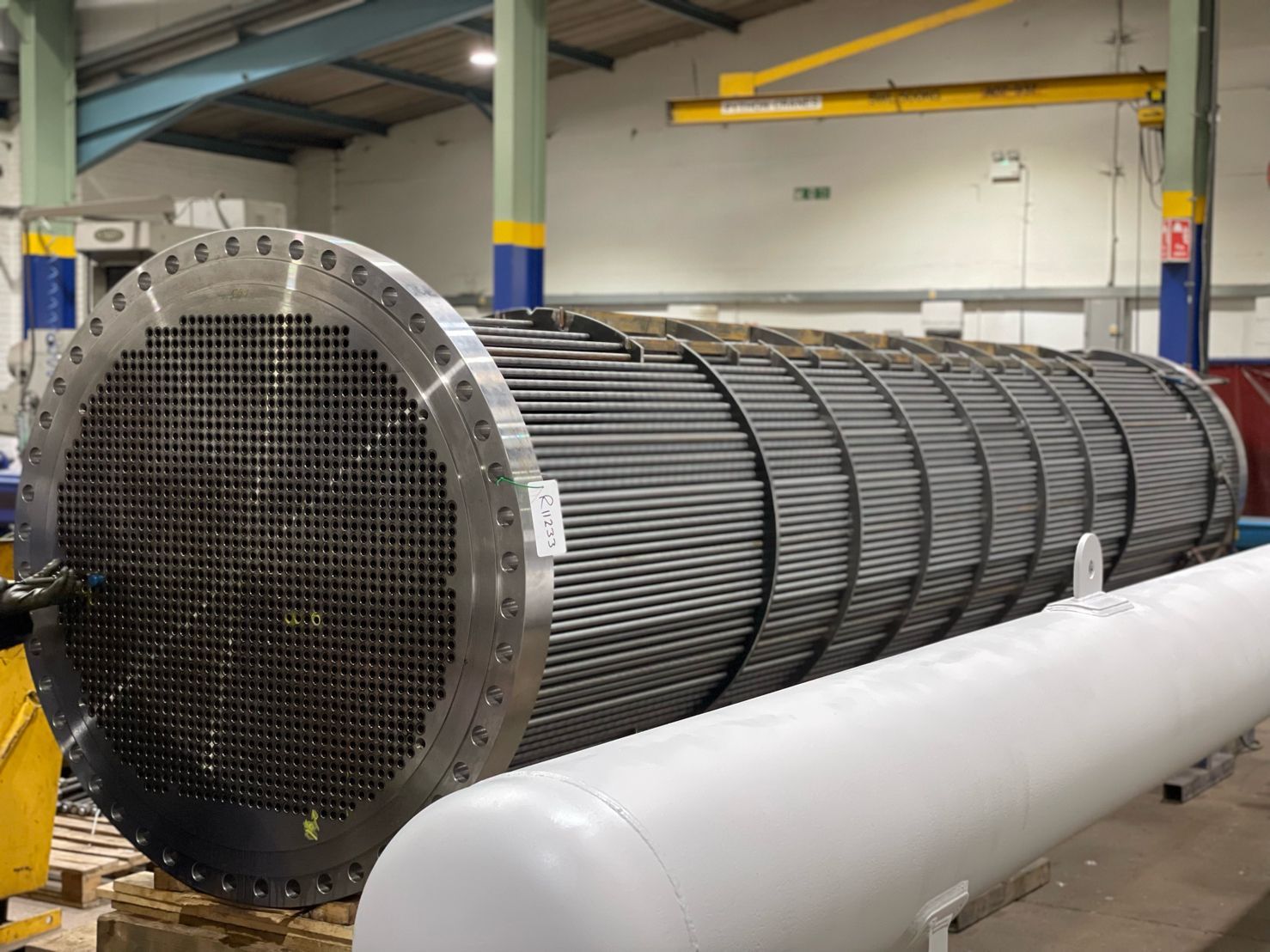
② U-shaped tube heat exchanger: it has only one tube plate, so the tube can be free to expand and contract when heated or cooled. The structure of this heat exchanger is simple, but the workload of manufacturing the bend is larger, and because the tube needs to have a certain bending radius, the utilization of the tube plate is poor, the tube is mechanically cleaned difficult to dismantle and replace the tubes is not easy, so it is required to pass through the tubes of the fluid is clean. This heat exchanger can be used for large temperature changes, high temperature or high pressure occasions.
③ packing box type heat exchanger: it has two forms, one is in the tube plate at the end of each tube has a separate packing seal to ensure that the free expansion and contraction of the tube, when the number of tubes in the heat exchanger is very small, before the use of this structure, but the distance between the tube than the general heat exchanger to be large, complex structure. Another form is made in one end of the tube and shell floating structure, in the floating place using the whole packing seal, the structure is simpler, but this structure is not easy to use in the case of large diameter, high pressure. Stuffing box type heat exchanger is rarely used now.
II. Review of design conditions:
1. heat exchanger design, the user should provide the following design conditions (process parameters):
① tube, shell program operating pressure (as one of the conditions to determine whether the equipment on the class, must be provided)
② tube, shell program operating temperature (inlet / outlet)
③ metal wall temperature (calculated by the process (provided by the user))
④Material name and characteristics
⑤Corrosion margin
⑥The number of programs
⑦ heat transfer area
⑧ heat exchanger tube specifications, arrangement (triangular or square)
⑨ folding plate or the number of support plate
⑩ insulation material and thickness (in order to determine the nameplate seat protruding height)
(11) Paint.
Ⅰ. If the user has special requirements, the user to provide brand, color
Ⅱ. Users have no special requirements, the designers themselves selected
2. Several key design conditions
① Operating pressure: as one of the conditions for determining whether the equipment is classified, it must be provided.
② material characteristics: if the user does not provide the name of the material must provide the degree of toxicity of the material.
Because the toxicity of the medium is related to the non-destructive monitoring of the equipment, heat treatment, the level of forgings for the upper class of equipment, but also related to the division of equipment:
a, GB150 10.8.2.1 (f) drawings indicate that the container holding extremely hazardous or highly hazardous medium of toxicity 100% RT.
b, 10.4.1.3 drawings indicate that containers holding extremely hazardous or highly hazardous media for toxicity should be post-weld heat treatment (welded joints of austenitic stainless steel may not be heat treated)
c. Forgings. The use of medium toxicity for extreme or highly hazardous forgings should meet the requirements of Class III or IV.
③ Pipe specifications:
Commonly used carbon steel φ19×2, φ25×2.5, φ32×3, φ38×5
Stainless steel φ19×2, φ25×2, φ32×2.5, φ38×2.5
Arrangement of heat exchanger tubes: triangle, corner triangle, square, corner square.
★ When mechanical cleaning is required between heat exchanger tubes, square arrangement should be used.
1. Design pressure, design temperature, welding joint coefficient
2. Diameter: DN < 400 cylinder, the use of steel pipe.
DN ≥ 400 cylinder, using steel plate rolled.
16" steel pipe ------ with the user to discuss the use of steel plate rolled.
3. Layout diagram:
According to the heat transfer area, heat transfer tube specifications to draw the layout diagram to determine the number of heat transfer tubes.
If the user provides a piping diagram, but also to review the piping is within the piping limit circle.
★Principle of pipe laying:
(1) in the piping limit circle should be full of pipe.
② the number of multi-stroke pipe should try to equalize the number of strokes.
③ Heat exchanger tube should be arranged symmetrically.
4. Material
When the tube plate itself has convex shoulder and is connected with cylinder (or head), forging should be used. Due to the use of such a structure of the tube plate are generally used for higher pressure, flammable, explosive, and toxicity for extreme, highly hazardous occasions, the higher requirements for the tube plate, the tube plate is also thicker. In order to avoid the convex shoulder to produce slag, delamination, and improve the convex shoulder fiber stress conditions, reduce the amount of processing, saving materials, the convex shoulder and the tube plate directly forged out of the overall forging to manufacture the tube plate.
5. Heat exchanger and tube plate connection
Tube in the tube plate connection, in the design of shell and tube heat exchanger is a more important part of the structure. He not only processing workload, and must make each connection in the operation of the equipment to ensure that the medium without leakage and withstand the medium pressure capacity.
Tube and tube plate connection are mainly the following three ways: a expansion; b welding; c expansion welding
Expansion for shell and tube between the media leakage will not cause adverse consequences of the situation, especially for the material weldability is poor (such as carbon steel heat exchanger tube) and the manufacturing plant's workload is too large.
Due to the expansion of the end of the tube in the welding plastic deformation, there is a residual stress, with the rise in temperature, the residual stress gradually disappears, so that the end of the tube to reduce the role of sealing and bonding, so the expansion of the structure by the pressure and temperature limitations, generally applicable to the design pressure ≤ 4Mpa, the design of the temperature ≤ 300 degrees, and in the operation of the no violent vibrations, no excessive temperature changes and no significant Stress corrosion.
Welding connection has the advantages of simple production, high efficiency and reliable connection. Through the welding, the tube to the tube plate has a better role in increasing; and also can reduce the pipe hole processing requirements, saving processing time, easy maintenance and other advantages, it should be used as a matter of priority.
In addition, when the medium toxicity is very large, the medium and the atmosphere mixed Easy to explode the medium is radioactive or inside and outside of the pipe material mixing will have an adverse effect, in order to ensure that the joints are sealed, but also often use the welding method. Welding method, although the advantages of many, because he can not completely avoid "crevice corrosion" and welded nodes of stress corrosion, and thin pipe wall and thick pipe plate is difficult to get a reliable weld between.
Welding method can be higher temperatures than expansion, but under the action of high temperature cyclic stress, the weld is very susceptible to fatigue cracks, tube and tube hole gap, when subjected to corrosive media, to accelerate the damage of the joint. Therefore, there is a welding and expansion joints used at the same time. This not only improves the fatigue resistance of the joint, but also reduces the tendency of crevice corrosion, and thus its service life is much longer than when welding alone is used.
In what occasions is suitable for the implementation of welding and expansion joints and methods, there is no uniform standard. Usually in the temperature is not too high but the pressure is very high or the medium is very easy to leak, the use of strength expansion and sealing weld (sealing weld refers to simply to prevent leakage and implementation of the weld, and does not guarantee the strength).
When the pressure and temperature are very high, the use of strength welding and paste expansion, (strength welding is even if the weld has a tight, but also to ensure that the joint has a large tensile strength, usually refers to the strength of the weld is equal to the strength of the pipe under axial load when the welding). The role of expansion is mainly to eliminate crevice corrosion and improve the fatigue resistance of the weld. Specific structural dimensions of the standard (GB/T151) has been stipulated, will not go into detail here.
For the pipe hole surface roughness requirements:
a, when the heat exchanger tube and tube plate welding connection, the tube surface roughness Ra value is not greater than 35uM.
b, a single heat exchanger tube and tube plate expansion connection, the tube hole surface roughness Ra value is not greater than 12.5uM expansion connection, the tube hole surface should not affect the expansion tightness of the defects, such as through the longitudinal or spiral scoring.
III. Design calculation
1. Shell wall thickness calculation (including pipe box short section, head, shell program cylinder wall thickness calculation) pipe, shell program cylinder wall thickness should meet the minimum wall thickness in GB151, for carbon steel and low alloy steel minimum wall thickness is according to the corrosion margin C2 = 1mm considerations for the case of C2 greater than 1mm, the minimum wall thickness of the shell should be increased accordingly.
2. Calculation of open hole reinforcement
For the shell using steel tube system, it is recommended to use the whole reinforcement (increase the cylinder wall thickness or use thick-walled tube); for the thicker tube box on the large hole to consider the overall economy.
Not another reinforcement should meet the requirements of several points:
① design pressure ≤ 2.5Mpa;
② The center distance between two adjacent holes should be not less than twice the sum of the diameter of the two holes;
③ Nominal diameter of the receiver ≤ 89mm;
④ take over the minimum wall thickness should be Table 8-1 requirements (take over the corrosion margin of 1mm).
3. Flange
Equipment flange using standard flange should pay attention to the flange and gasket, fasteners match, otherwise the flange should be calculated. For example, type A flat welding flange in the standard with its matching gasket for non-metallic soft gasket; when the use of winding gasket should be recalculated for the flange.
4. Pipe plate
Need to pay attention to the following issues:
① tube plate design temperature: According to the provisions of GB150 and GB/T151, should be taken not less than the metal temperature of the component, but in the calculation of the tube plate can not guarantee that the tube shell process media role, and the metal temperature of the tube plate is difficult to calculate, it is generally taken on the higher side of the design temperature for the design temperature of the tube plate.
② multi-tube heat exchanger: in the range of piping area, due to the need to set up the spacer groove and tie rod structure and failed to be supported by the heat exchanger area Ad: GB/T151 formula.
③The effective thickness of the tube plate
The effective thickness of the tube plate refers to the pipe range separation of the bottom of the bulkhead groove thickness of the tube plate minus the sum of the following two things
a, pipe corrosion margin beyond the depth of the depth of the pipe range partition groove part
b, shell program corrosion margin and tube plate in the shell program side of the structure of the groove depth of the two largest plants
5. Expansion joints set
In the fixed tube and plate heat exchanger, due to the temperature difference between the fluid in the tube course and the tube course fluid, and the heat exchanger and shell and tube plate fixed connection, so that in the use of the state, the shell and tube expansion difference exists between the shell and the tube, the shell and tube to axial load. In order to avoid shell and heat exchanger damage, heat exchanger destabilization, heat exchanger tube from the tube plate pull off, it should be set up expansion joints to reduce the shell and heat exchanger axial load.
Generally in the shell and heat exchanger wall temperature difference is large, need to consider setting the expansion joint, in the tube plate calculation, according to the temperature difference between the various common conditions calculated σt, σc, q, one of which fails to qualify, it is necessary to increase the expansion joint.
σt - axial stress of the heat exchanger tube
σc - shell process cylinder axial stress
q--The heat exchanger tube and tube plate connection of the pull-off force
IV. Structural Design
1. Pipe box
(1) Length of pipe box
a. Minimum inner depth
① to the opening of the single pipe course of the tube box, the minimum depth at the center of the opening should not be less than 1 / 3 of the inner diameter of the receiver;
② the inner and outer depth of the pipe course should ensure that the minimum circulation area between the two courses is not less than 1.3 times the circulation area of the heat exchanger tube per course;
b, the maximum inside depth
Consider whether it is convenient to weld and clean up the inner parts, especially for the nominal diameter of the smaller multi-tube heat exchanger.
(2) Separate program partition
Thickness and arrangement of the partition according to GB151 Table 6 and Figure 15, for the thickness greater than 10mm of the partition, the sealing surface should be trimmed to 10mm; for the tube heat exchanger, the partition should be set up on the tear hole (drain hole), drain hole diameter is generally 6mm.
2. Shell and tube bundle
①Tube bundle level
Ⅰ, Ⅱ level tube bundle, only for carbon steel, low alloy steel heat exchanger tube domestic standards, there are still "higher level" and "ordinary level" developed. Once the domestic heat exchanger tube can be used "higher" steel pipe, carbon steel, low alloy steel heat exchanger tube bundle need not be divided into Ⅰ and Ⅱ level!
Ⅰ, Ⅱ tube bundle of the difference lies mainly in the heat exchanger tube outside diameter, wall thickness deviation is different, the corresponding hole size and deviation is different.
Grade Ⅰ tube bundle of higher precision requirements, for stainless steel heat exchanger tube, only Ⅰ tube bundle; for the commonly used carbon steel heat exchanger tube
② Tube plate
a, tube hole size deviation
Note the difference between Ⅰ, Ⅱ level tube bundle
b, the program partition groove
Ⅰ slot depth is generally not less than 4mm
Ⅱ sub-program partition slot width: carbon steel 12mm; stainless steel 11mm
Ⅲ minute range partition slot corner chamfering is generally 45 degrees, chamfering width b is approximately equal to the radius R of the corner of the minute range gasket.
③Folding plate
a. Pipe hole size: differentiated by bundle level
b, bow folding plate notch height
Notch height should be so that the fluid through the gap with the flow rate across the tube bundle similar to the notch height is generally taken 0.20-0.45 times the inner diameter of the rounded corner, notch is generally cut in the pipe row below the center line or cut in two rows of pipe holes between the small bridge (to facilitate the convenience of wearing a pipe).
c. Notch orientation
One-way clean fluid, notch up and down arrangement;
Gas containing a small amount of liquid, notch upward towards the lowest part of the folding plate to open the liquid port;
Liquid containing a small amount of gas, notch down towards the highest part of the folding plate to open the ventilation port
Gas-liquid coexistence or the liquid contains solid materials, notch left and right arrangement, and open the liquid port in the lowest place
d. Minimum thickness of folding plate; maximum unsupported span
e. The folding plates at both ends of the tube bundle are as close as possible to the shell inlet and outlet receivers.
④Tie rod
a, the diameter and number of tie rods
Diameter and number according to Table 6-32, 6-33 selection, in order to ensure that greater than or equal to the cross-sectional area of the tie rod given in Table 6-33 under the premise of the diameter and number of tie rods can be changed, but its diameter shall not be less than 10mm, the number of not less than four
b, the tie rod should be arranged as uniformly as possible in the outer edge of the tube bundle, for large diameter heat exchanger, in the pipe area or near the folding plate gap should be arranged in an appropriate number of tie rods, any folding plate should be not less than 3 support points
c. Tie rod nut, some users require the following a nut and folding plate welding
⑤ Anti-flush plate
a. The setup of anti-flush plate is to reduce the uneven distribution of fluid and the erosion of the heat exchanger tube end.
b. Fixing method of anti-washout plate
As far as possible fixed in the fixed-pitch tube or near the tube plate of the first folding plate, when the shell inlet is located in the non-fixed rod on the side of the tube plate, the anti-scrambling plate can be welded to the cylinder body
(6) Setting of expansion joints
a. Located between the two sides of the folding plate
In order to reduce the fluid resistance of the expansion joint, if necessary, in the expansion joint on the inside of a liner tube, the liner tube should be welded to the shell in the direction of the fluid flow, for vertical heat exchangers, when the fluid flow direction upward, should be set up at the lower end of the liner tube discharge holes
b. Expansion joints of the protective device to prevent the equipment in the transportation process or the use of pulling the bad
(vii) the connection between the tube plate and the shell
a. Extension doubles as a flange
b. Pipe plate without flange (GB151 Appendix G)
3. Pipe flange:
① design temperature greater than or equal to 300 degrees, should be used butt flange.
② for the heat exchanger can not be used to take over the interface to give up and discharge, should be set in the tube, the highest point of the shell course of the bleeder, the lowest point of the discharge port, the minimum nominal diameter of 20mm.
③ Vertical heat exchanger can be set up overflow port.
4. Support: GB151 species according to the provisions of Article 5.20.
5. Other accessories
① Lifting lugs
Quality greater than 30Kg official box and pipe box cover should be set lugs.
② top wire
In order to facilitate the dismantling of the pipe box, pipe box cover, should be set in the official board, pipe box cover top wire.
V. Manufacturing, inspection requirements
1. Pipe plate
① spliced tube plate butt joints for 100% ray inspection or UT, qualified level: RT: Ⅱ UT: Ⅰ level;
② In addition to stainless steel, spliced pipe plate stress relief heat treatment;
③ tube plate hole bridge width deviation: according to the formula for calculating the width of the hole bridge: B = (S - d) - D1
Minimum width of the hole bridge: B = 1/2 (S - d) + C;
2. Tube box heat treatment:
Carbon steel, low alloy steel welded with a split-range partition of the pipe box, as well as the pipe box of the lateral openings more than 1/3 of the inner diameter of the cylinder pipe box, in the application of welding for stress relief heat treatment, flange and partition sealing surface should be processed after heat treatment.
3. Pressure test
When the shell process design pressure is lower than the tube process pressure, in order to check the quality of the heat exchanger tube and tube plate connections
① Shell program pressure to increase the test pressure with the pipe program consistent with the hydraulic test, to check whether the leakage of pipe joints. (However, it is necessary to ensure that the primary film stress of the shell during the hydraulic test is ≤0.9ReLΦ)
② When the above method is not appropriate, the shell can be hydrostatic test according to the original pressure after passing, and then the shell for ammonia leakage test or halogen leakage test.
VI. Some issues to be noted on the charts
1. Indicate the level of tube bundle
2. Heat exchanger tube should be written labeling number
3. Tube plate piping contour line outside the closed thick solid line
4. Assembly drawings should be labeled folding plate gap orientation
5. Standard expansion joint discharge holes, exhaust holes on the pipe joints, pipe plugs should be out of the picture
Post time: Oct-11-2023