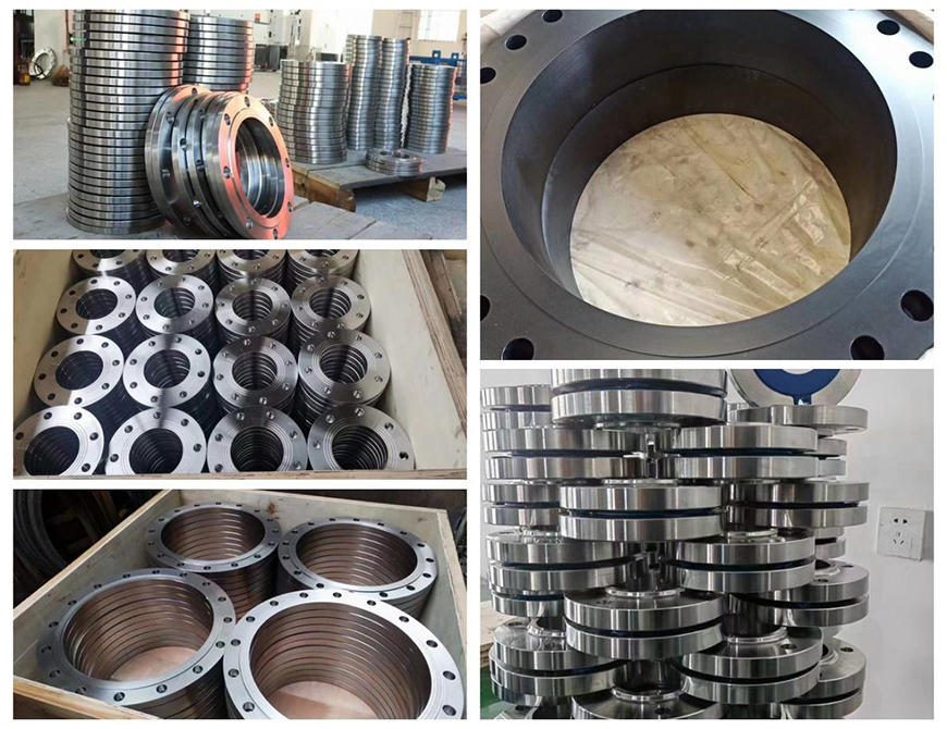
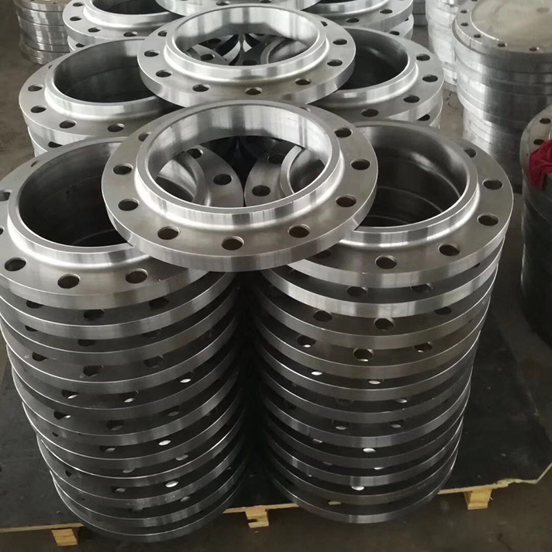
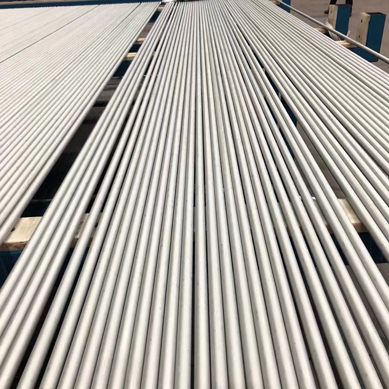
Product Description
Standard Information - ASME/ANSI B16.5 & B16.47 - Pipe Flanges and Flanged Fittings
The ASME B16.5 standard covers various aspects of pipe flanges and flanged fittings, including pressure-temperature ratings, materials, dimensions, tolerances, marking, testing, and designating openings for these components. This standard includes flanges with rating class designations ranging from 150 to 2500, covering sizes from NPS 1/2 through NPS 24. It provides requirements in both metric and U.S units. It's important to note that this standard is limited to flanges and flanged fittings made from cast or forged materials, including blind flanges and specific reducing flanges made from cast, forged, or plate materials.
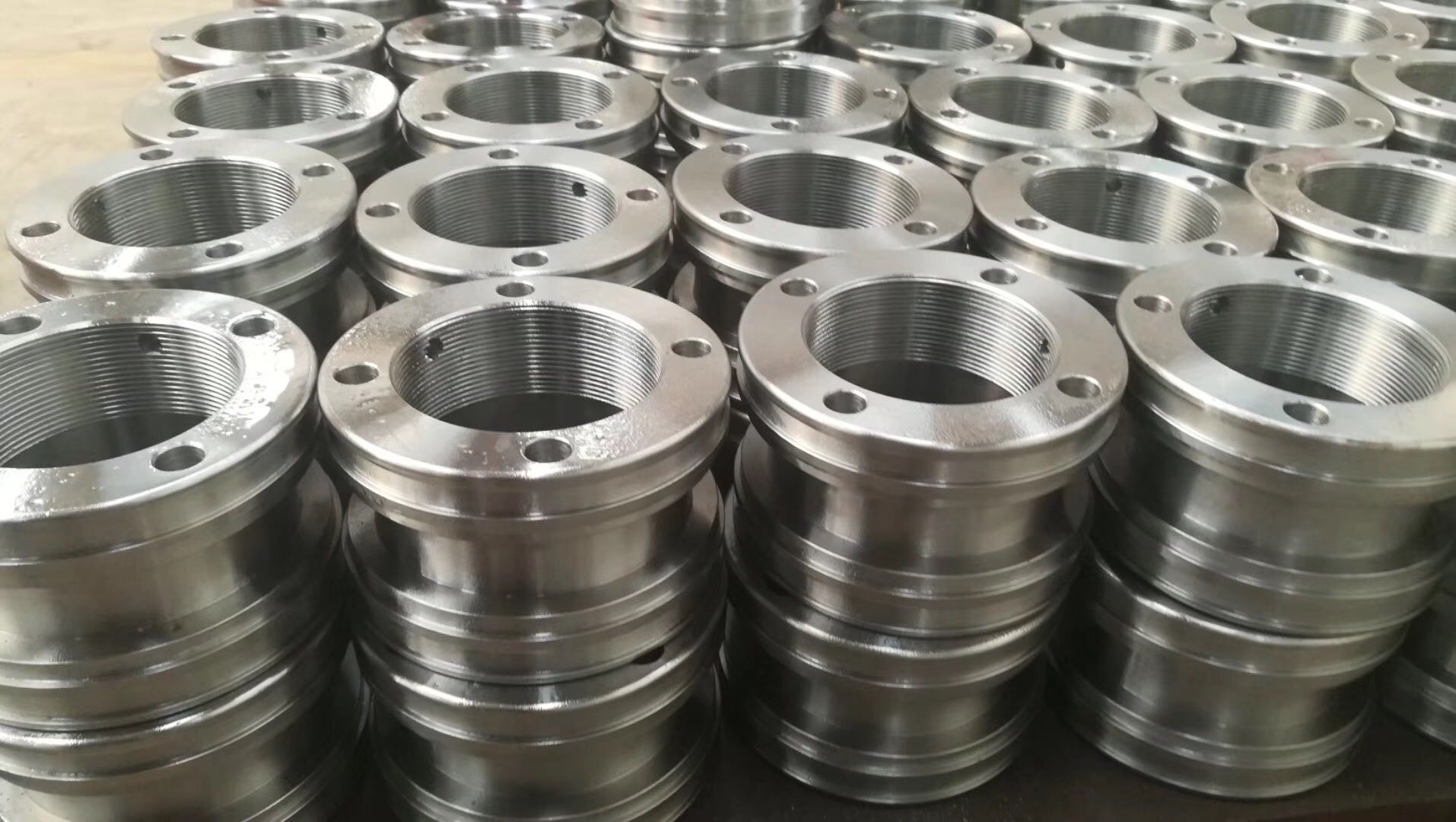
For pipe flanges and flanged fittings larger than 24" NPS, ASME/ANSI B16.47 should be referenced.
Common Flange Types
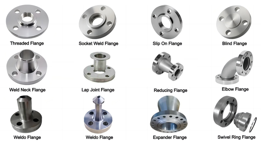
● Slip-On Flanges: These flanges are commonly stocked in ANSI Class 150, 300, 600, 1500 & 2500 up to 24" NPS. They are "slipped over" the pipe or fitting ends and welded in position, allowing for fillet welds both inside and outside the flange. Reduction versions are used to reduce line sizes when space is limited.
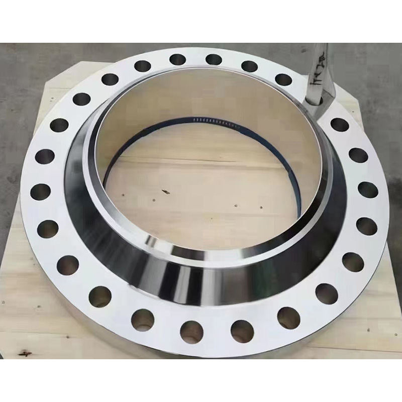
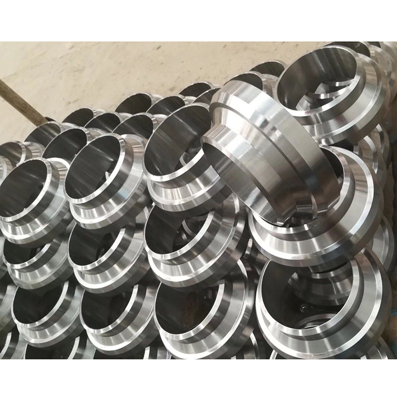
● Weld Neck Flanges: These flanges have a distinct long tapered hub and a smooth transition of thickness, ensuring a full penetration weld connection to the pipe or fitting. They are used in severe service conditions.
● Lap Joint Flanges: Paired with a stub end, lap joint flanges are slipped over the stub end fitting and connected by welding or other means. Their loose design allows for easy alignment during assembly and disassembly.
● Backing Flanges: These flanges lack a raised face and are used with backing rings, providing cost-effective solutions for flange connections.
● Threaded (Screwed) Flanges: Bored to match specific pipe inside diameters, threaded flanges are machined with tapered pipe threads on the reverse side, primarily for smaller bore pipes.
● Socket Weld Flanges: Resembling slip-on flanges, socket weld flanges are machined to match pipe size sockets, allowing fillet welding on the back side to secure the connection. They are typically used for smaller bore pipes.
● Blind Flanges: These flanges have no center hole and are used to close or block the end of a piping system.
These are some of the common types of pipe flanges used in various industrial and commercial applications. The choice of flange type depends on factors like the pressure, temperature, and type of fluid being transported, as well as specific project requirements. Proper selection and installation of flanges are crucial for the safe and efficient operation of piping systems.
Specifications
| ASME B16.5: Carbon Steel, Stainless Steel, Alloy Steel |
| EN 1092-1: Carbon Steel, Stainless Steel, Alloy Steel |
| DIN 2501: Carbon Steel, Stainless Steel, Alloy Steel |
| GOST 33259: Carbon Steel, Stainless Steel, Alloy Steel |
| SABS 1123: Carbon Steel, Stainless Steel, Alloy Steel |
Flange Materials
Flanges are welded to pipe and equipment nozzle. Accordingly, it is manufactured from the following materials;
● Carbon steel
● Low alloy steel
● Stainless steel
● Combination of Exotic materials (Stub) and other backing materials
The list of materials used in manufacturing is covered in ASME B16.5 & B16.47.
● ASME B16.5 -Pipe Flanges and Flanged Fittings NPS ½” to 24”
● ASME B16.47 -Large Diameter Steel Flanges NPS 26” to 60”
Commonly used Forged material grads are
● Carbon Steel: – ASTM A105, ASTM A350 LF1/2, ASTM A181
● Alloy Steel: – ASTM A182F1 /F2 /F5 /F7 /F9 /F11 /F12 /F22
● Stainless Steel: – ASTM A182F6 /F304 /F304L /F316 /F316L/ F321/F347/F348
Class 150 Slip-on Flange Dimensions
|
Size in Inch |
Size in mm |
Outer Dia. |
Flange Thick. |
Hub OD |
Flange Length |
RF Dia. |
RF Height |
PCD |
Socket Bore |
No of Bolts |
Bolt Size UNC |
Machine Bolt Length |
RF Stud Length |
Hole Size |
ISO Stud Size |
Weight in kg |
|
|
|
A |
B |
C |
D |
E |
F |
G |
H |
|
|
|
|
|
|
|
|
1/2 |
15 |
90 |
9.6 |
30 |
14 |
34.9 |
2 |
60.3 |
22.2 |
4 |
1/2 |
50 |
55 |
5/8 |
M14 |
0.8 |
|
3/4 |
20 |
100 |
11.2 |
38 |
14 |
42.9 |
2 |
69.9 |
27.7 |
4 |
1/2 |
50 |
65 |
5/8 |
M14 |
0.9 |
|
1 |
25 |
110 |
12.7 |
49 |
16 |
50.8 |
2 |
79.4 |
34.5 |
4 |
1/2 |
55 |
65 |
5/8 |
M14 |
0.9 |
|
1 1/4 |
32 |
115 |
14.3 |
59 |
19 |
63.5 |
2 |
88.9 |
43.2 |
4 |
1/2 |
55 |
70 |
5/8 |
M14 |
1.4 |
|
1 1/2 |
40 |
125 |
15.9 |
65 |
21 |
73 |
2 |
98.4 |
49.5 |
4 |
1/2 |
65 |
70 |
5/8 |
M14 |
1.4 |
|
2 |
50 |
150 |
17.5 |
78 |
24 |
92.1 |
2 |
120.7 |
61.9 |
4 |
5/8 |
70 |
85 |
3/4 |
M16 |
2.3 |
|
2 1/2 |
65 |
180 |
20.7 |
90 |
27 |
104.8 |
2 |
139.7 |
74.6 |
4 |
5/8 |
75 |
90 |
3/4 |
M16 |
3.2 |
|
3 |
80 |
190 |
22.3 |
108 |
29 |
127 |
2 |
152.4 |
90.7 |
4 |
5/8 |
75 |
90 |
3/4 |
M16 |
3.7 |
|
3 1/2 |
90 |
215 |
22.3 |
122 |
30 |
139.7 |
2 |
177.8 |
103.4 |
8 |
5/8 |
75 |
90 |
3/4 |
M16 |
5 |
|
4 |
100 |
230 |
22.3 |
135 |
32 |
157.2 |
2 |
190.5 |
116.1 |
8 |
5/8 |
75 |
90 |
3/4 |
M16 |
5.9 |
|
5 |
125 |
255 |
22.3 |
164 |
35 |
185.7 |
2 |
215.9 |
143.8 |
8 |
3/4 |
85 |
95 |
7/8 |
M20 |
6.8 |
|
6 |
150 |
280 |
23.9 |
192 |
38 |
215.9 |
2 |
241.3 |
170.7 |
8 |
3/4 |
85 |
100 |
7/8 |
M20 |
8.6 |
|
8 |
200 |
345 |
27 |
246 |
43 |
269.9 |
2 |
298.5 |
221.5 |
8 |
3/4 |
90 |
110 |
7/8 |
M20 |
13.7 |
|
10 |
250 |
405 |
28.6 |
305 |
48 |
323.8 |
2 |
362 |
276.2 |
12 |
7/8 |
100 |
115 |
1 |
M24 |
19.5 |
|
12 |
300 |
485 |
30.2 |
365 |
54 |
381 |
2 |
431.8 |
327 |
12 |
7/8 |
100 |
120 |
1 |
M24 |
29 |
|
14 |
350 |
535 |
33.4 |
400 |
56 |
412.8 |
2 |
476.3 |
359.2 |
12 |
1 |
115 |
135 |
1 1/8 |
M27 |
41 |
|
16 |
400 |
595 |
35 |
457 |
62 |
469.9 |
2 |
539.8 |
410.5 |
16 |
1 |
115 |
135 |
1 1/8 |
M27 |
54 |
|
18 |
450 |
635 |
38.1 |
505 |
67 |
533.4 |
2 |
577.9 |
461.8 |
16 |
1 1/8 |
125 |
145 |
1 1/4 |
M30 |
59 |
|
20 |
500 |
700 |
41.3 |
559 |
71 |
584.2 |
2 |
635 |
513.1 |
20 |
1 1/8 |
140 |
160 |
1 1/4 |
M30 |
75 |
|
24 |
600 |
815 |
46.1 |
663 |
81 |
692.2 |
2 |
749.3 |
616 |
20 |
1 1/4 |
150 |
170 |
1 3/8 |
M33 |
100 |
Class 150 Weld Neck Flange Dimensions
|
Size in Inch |
Size in mm |
Outer Diameter |
Flange Thickness |
Hub OD |
Weld Neck OD |
Welding Neck Length |
Bore |
RF Diameter |
RF Height |
PCD |
Weld Face |
|
|
|
A |
B |
C |
D |
E |
F |
G |
H |
I |
J |
|
1/2 |
15 |
90 |
9.6 |
30 |
21.3 |
46 |
Welding Neck bore is derived from the pipe schedule |
34.9 |
2 |
60.3 |
1.6 |
|
3/4 |
20 |
100 |
11.2 |
38 |
26.7 |
51 |
42.9 |
2 |
69.9 |
1.6 |
|
|
1 |
25 |
110 |
12.7 |
49 |
33.4 |
54 |
50.8 |
2 |
79.4 |
1.6 |
|
|
1 1/4 |
32 |
115 |
14.3 |
59 |
42.2 |
56 |
63.5 |
2 |
88.9 |
1.6 |
|
|
1 1/2 |
40 |
125 |
15.9 |
65 |
48.3 |
60 |
73 |
2 |
98.4 |
1.6 |
|
|
2 |
50 |
150 |
17.5 |
78 |
60.3 |
62 |
92.1 |
2 |
120.7 |
1.6 |
|
|
2 1/2 |
65 |
180 |
20.7 |
90 |
73 |
68 |
104.8 |
2 |
139.7 |
1.6 |
|
|
3 |
80 |
190 |
22.3 |
108 |
88.9 |
68 |
127 |
2 |
152.4 |
1.6 |
|
|
3 1/2 |
90 |
215 |
22.3 |
122 |
101.6 |
70 |
139.7 |
2 |
177.8 |
1.6 |
|
|
4 |
100 |
230 |
22.3 |
135 |
114.3 |
75 |
157.2 |
2 |
190.5 |
1.6 |
|
|
5 |
125 |
255 |
22.3 |
164 |
141.3 |
87 |
185.7 |
2 |
215.9 |
1.6 |
|
|
6 |
150 |
280 |
23.9 |
192 |
168.3 |
87 |
215.9 |
2 |
241.3 |
1.6 |
|
|
8 |
200 |
345 |
27 |
246 |
219.1 |
100 |
269.9 |
2 |
298.5 |
1.6 |
|
|
10 |
250 |
405 |
28.6 |
305 |
273 |
100 |
323.8 |
2 |
362 |
1.6 |
|
|
12 |
300 |
485 |
30.2 |
365 |
323.8 |
113 |
381 |
2 |
431.8 |
1.6 |
|
|
14 |
350 |
535 |
33.4 |
400 |
355.6 |
125 |
412.8 |
2 |
476.3 |
1.6 |
|
|
16 |
400 |
595 |
35 |
457 |
406.4 |
125 |
469.9 |
2 |
539.8 |
1.6 |
|
|
18 |
450 |
635 |
38.1 |
505 |
457.2 |
138 |
533.4 |
2 |
577.9 |
1.6 |
|
|
20 |
500 |
700 |
41.3 |
559 |
508 |
143 |
584.2 |
2 |
635 |
1.6 |
|
|
24 |
600 |
815 |
46.1 |
663 |
610 |
151 |
692.2 |
2 |
749.3 |
1.6 |
Class 150 Blind Flange Dimensions
|
Size |
Size |
Outer |
Flange |
RF |
RF |
PCD |
No of |
Bolt Size |
Machine Bolt |
RF Stud |
Hole Size |
ISO Stud |
Weight |
|
A |
B |
C |
D |
E |
|||||||||
|
1/2 |
15 |
90 |
9.6 |
34.9 |
2 |
60.3 |
4 |
1/2 |
50 |
55 |
5/8 |
M14 |
0.9 |
|
3/4 |
20 |
100 |
11.2 |
42.9 |
2 |
69.9 |
4 |
1/2 |
50 |
65 |
5/8 |
M14 |
0.9 |
|
1 |
25 |
110 |
12.7 |
50.8 |
2 |
79.4 |
4 |
1/2 |
55 |
65 |
5/8 |
M14 |
0.9 |
|
1 1/4 |
32 |
115 |
14.3 |
63.5 |
2 |
88.9 |
4 |
1/2 |
55 |
70 |
5/8 |
M14 |
1.4 |
|
1 1/2 |
40 |
125 |
15.9 |
73 |
2 |
98.4 |
4 |
1/2 |
65 |
70 |
5/8 |
M14 |
1.8 |
|
2 |
50 |
150 |
17.5 |
92.1 |
2 |
120.7 |
4 |
5/8 |
70 |
85 |
3/4 |
M16 |
2.3 |
|
2 1/2 |
65 |
180 |
20.7 |
104.8 |
2 |
139.7 |
4 |
5/8 |
75 |
90 |
3/4 |
M16 |
3.2 |
|
3 |
80 |
190 |
22.3 |
127 |
2 |
152.4 |
4 |
5/8 |
75 |
90 |
3/4 |
M16 |
4.1 |
|
3 1/2 |
90 |
215 |
22.3 |
139.7 |
2 |
177.8 |
8 |
5/8 |
75 |
90 |
3/4 |
M16 |
5.9 |
|
4 |
100 |
230 |
22.3 |
157.2 |
2 |
190.5 |
8 |
5/8 |
75 |
90 |
3/4 |
M16 |
7.7 |
|
5 |
125 |
255 |
22.3 |
185.7 |
2 |
215.9 |
8 |
3/4 |
85 |
95 |
7/8 |
M20 |
9.1 |
|
6 |
150 |
280 |
23.9 |
215.9 |
2 |
241.3 |
8 |
3/4 |
85 |
100 |
7/8 |
M20 |
11.8 |
|
8 |
200 |
345 |
27 |
269.9 |
2 |
298.5 |
8 |
3/4 |
90 |
110 |
7/8 |
M20 |
20.5 |
|
10 |
250 |
405 |
28.6 |
323.8 |
2 |
362 |
12 |
7/8 |
100 |
115 |
1 |
M24 |
32 |
|
12 |
300 |
485 |
30.2 |
381 |
2 |
431.8 |
12 |
7/8 |
100 |
120 |
1 |
M24 |
50 |
|
14 |
350 |
535 |
33.4 |
412.8 |
2 |
476.3 |
12 |
1 |
115 |
135 |
1 1/8 |
M27 |
64 |
|
16 |
400 |
595 |
35 |
469.9 |
2 |
539.8 |
16 |
1 |
115 |
135 |
1 1/8 |
M27 |
82 |
|
18 |
450 |
635 |
38.1 |
533.4 |
2 |
577.9 |
16 |
1 1/8 |
125 |
145 |
1 1/4 |
M30 |
100 |
|
20 |
500 |
700 |
41.3 |
584.2 |
2 |
635 |
20 |
1 1/8 |
140 |
160 |
1 1/4 |
M30 |
130 |
|
24 |
600 |
815 |
46.1 |
692.2 |
2 |
749.3 |
20 |
1 1/4 |
150 |
170 |
1 3/8 |
M33 |
196 |
Standard & Grade
|
ASME B16.5: Pipe Flanges and Flanged Fittings |
Materials: Carbon Steel, Stainless Steel, Alloy Steel |
|
EN 1092-1: Flanges and Their Joints - Circular Flanges for Pipes, Valves, Fittings, and Accessories, PN Designated - Part 1: Steel Flanges |
Materials: Carbon Steel, Stainless Steel, Alloy Steel
|
|
DIN 2501: Flanges and Lapped Joints |
Materials: Carbon Steel, Stainless Steel, Alloy Steel |
|
GOST 33259: Flanges for Valves, Fittings, and Pipelines for Pressure to PN 250 |
Materials: Carbon Steel, Stainless Steel, Alloy Steel |
|
SABS 1123: Flanges for Pipes, Valves, and Fittings |
Materials: Carbon Steel, Stainless Steel, Alloy Steel |
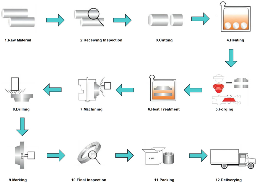
Manufacturing Process
Quality Control
Raw Material Checking, Chemical Analysis, Mechanical Test, Visual Inspection, Dimension Check, Bend Test , Flattening Test, Impact Test, DWT Test, Non-Destructive Examination(UT, MT, PT, X-Ray, ), Hardness Test, Pressure Testing, Seat Leakage Testing, Metallography Testing, Corrosion Testing, Fire Resistance Testing, Salt Spray Testing, Flow Performance Testing, Torque and Thrust Testing, Painting and Coating Inspection, Documentation Review…..
Usage & Application
Flanges are important industrial parts used to connect pipes, valves, equipment and other piping components. They play a key role in connecting, supporting and sealing piping systems.Flanges serve as crucial components in various industrial applications, including:
● Piping Systems
● Valves
● Equipment
● Connections
● Sealing
● Pressure Management
Packing & Shipping
At Womic Steel, we understand the importance of secure packaging and reliable shipping when it comes to delivering our high-quality pipe fittings to your doorstep. Here's an overview of our packaging and shipping procedures for your reference:
Packaging:
Our pipe flanges are carefully packaged to ensure they reach you in perfect condition, ready for your industrial or commercial needs. Our packaging process includes the following key steps:
● Quality Inspection: Before packaging, all flanges undergo a thorough quality inspection to confirm they meet our stringent standards for performance and integrity.
● Protective Coating: Depending on the type of material and application, our flanges may receive a protective coating to prevent corrosion and damage during transportation.
● Secure Bundling: Flanges are bundled together securely, ensuring they remain stable and protected throughout the shipping process.
● Labeling and Documentation: Each package is clearly labeled with essential information, including product specifications, quantity, and any special handling instructions. Relevant documentation, such as certificates of compliance, is also included.
● Custom Packaging: We can accommodate special packaging requests based on your unique requirements, ensuring your flanges are prepared exactly as needed.
Shipping:
We collaborate with reputable shipping partners to guarantee reliable and timely delivery to your specified destination.Our logistics team optimizes shipping routes to minimize transit times and reduce the risk of delays.For international shipments, we handle all necessary customs documentation and compliance to facilitate smooth customs clearance.We offer flexible shipping options, including expedited shipping for urgent requirements.
